HKUST CSIT5401 Recognition System lecture notes 4. 识别系统复习笔记。
- Fingerprint image acquisition systems
- Minutiae
- Fingerprint Enhancement
- Fingerprint Matching
- FingerCode
Fingerprint image acquisition systems
Fingerprint matching (recognition) is the most popular biometric technique used in automatic personal identification. The main reason for the popularity of fingerprints as a form of identification is that the fingerprint of a person is unique and remains invariant with his or her age.
There are three kinds of sensing devices typically: optical sensors, solid-state sensors and ultrasound sensors.
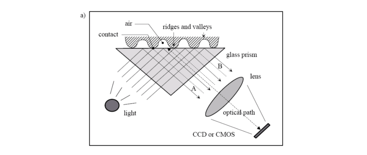
Optical sensors
The finger touches the top side of a glass prism. The left side of the prism is illustrated through a diffused light. The light entering the prism is reflected at the valleys, and absorbed at the ridges. The lack of reflection allows the ridges to be discriminated from the valleys. The light rays exit from the right side of the prism and are focused through a lens onto an image sensor.
Solid-state sensors
All silicon-based sensors consist of an array of pixels, each pixel being a tiny sensor itself. The user directly touches the surface of the silicon. The physical information is converted into electrical signals by using the capacitive sensor (other kinds of sensor can also be used, e.g., thermal, electric field and piezoelectric).
The capacitive sensor is a 2D array of micro-capacitor plates embedded in a chip. The other plate of each micro-capacitor is the finger skin itself.
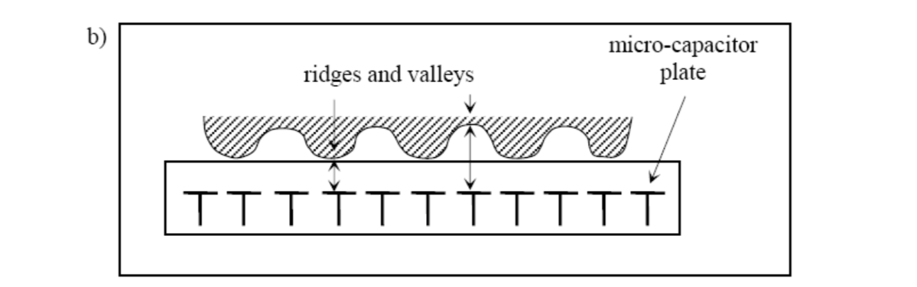
Small electrical charges are created between the surface of the finger and each of the silicon plates when a finger is placed on the chip. The magnitude of these electrical charges depends on the distance between the fingerprint surface and the capacitance plates.
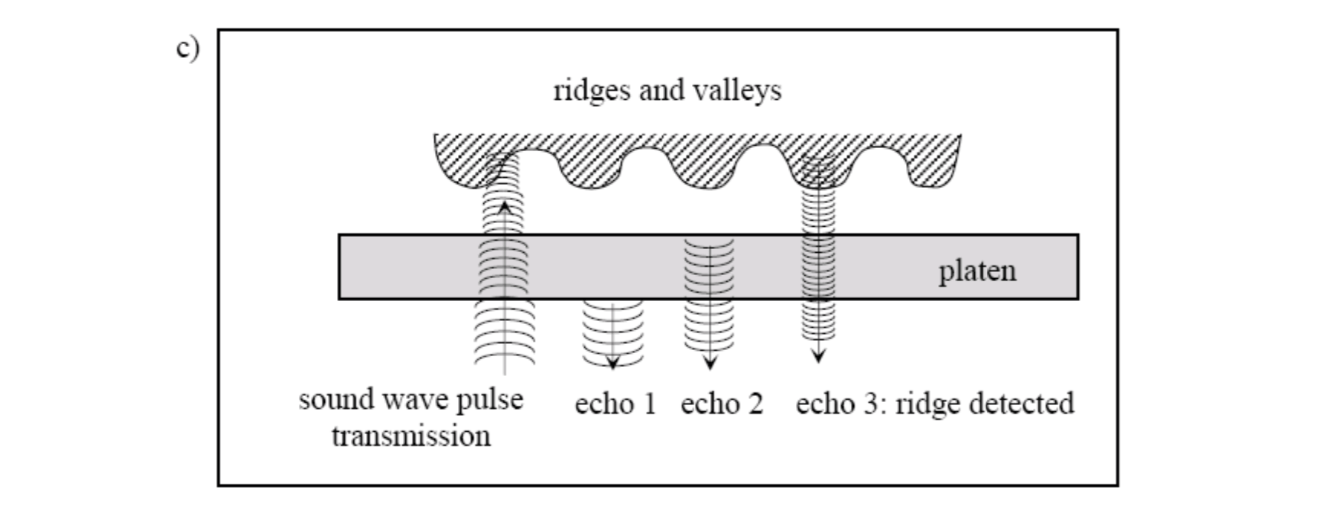
Ultrasound sensors
An ultrasound sensor is based on sending acoustic signals toward the fingertip and capturing the echo signal. The echo signal is used to compute the range image of the fingerprint and, subsequently, the ridge structure itself.
Minutiae
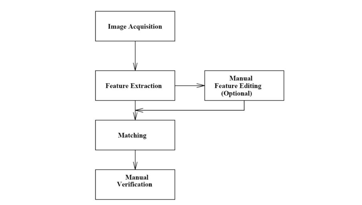
An automatic fingerprint identification system (AFIS) consists of various processing stages.
In AFIS, the high-level structural features (ridges and valleys) are extracted from the fingerprint image for the purpose of representation and matching. The ridges and valleys in a fingerprint alternate, flowing in a local constant direction.
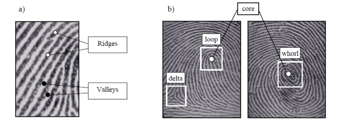
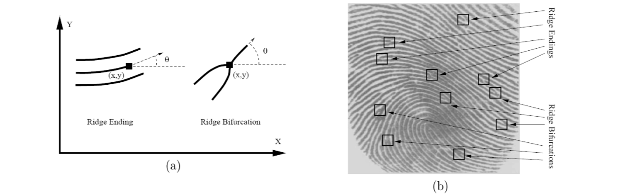
The ridges (or the valleys) exhibit anomalies of various kinds, such as ridge bifurcations, ridge endings, short ridges, and ridge crossovers. These features are called minutiae.
In a good quality rolled fingerprint image, there are about 70 to 80 minutia points and in a latent fingerprint the number of minutiae is much less (approximately 20 to 30 minutia points). Commercially available fingerprint identification systems typically use ridge bifurcations and ridge endings as features.

- A ridge ending is defined as the point where a ridge ends abruptly.
- A ridge bifurcation is defined as the point where a ridge diverges into branch ridges.
A critical step in fingerprint matching is to automatically and reliably extract minutiae from the input fingerprint images, which is a difficult task.
Fingerprint Enhancement
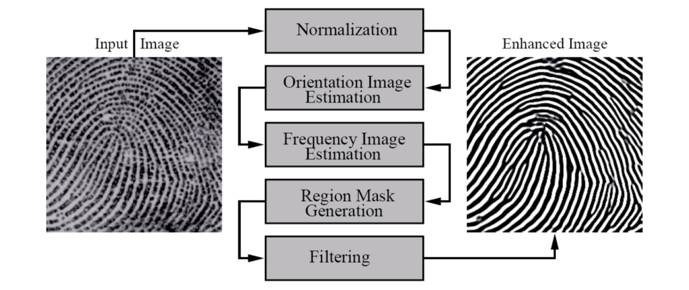
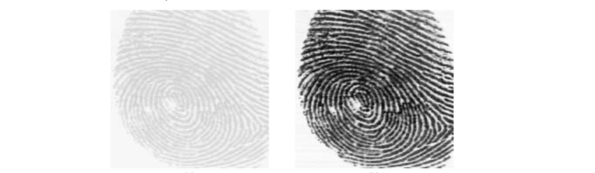
Fingerprint images can be of very poor quality. An enhancement algorithm which can improve the clarity of the ridge structure is therefore necessary.
The flowchart of the fingerprint enhancement algorithm is shown below.
Normalization
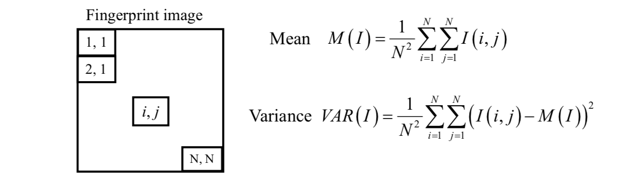
A gray-level fingerprint image \(I\) is defined as an \(N \times N\) matrix. At the \(i\) th row and \(j\) th column, the intensity of the pixel is \(I(i, j)\). It is assumed that the fingerprint images are scanned at a resolution of 500 dots per inch (dpi), which is the resolution recommended by FBI.
The mean and variance of a gray-level fingerprint image are defined as
An input fingerprint image is normalized so that it has a pre-specified mean \(M_0\) and variance \(\text{VAR}_0\).
The normalized image \(G(i,j)\) is defined as \[
G(i,j)=\begin{cases}
M_0+\sqrt{\frac{VAR_0(I(i,j)-M)^2}{VAR}} &\text{if }I(i,j)>M\\
M_0-\sqrt{\frac{VAR_0(I(i,j)-M)^2}{VAR}}&\text{otherwise}\\
\end{cases}
\] 
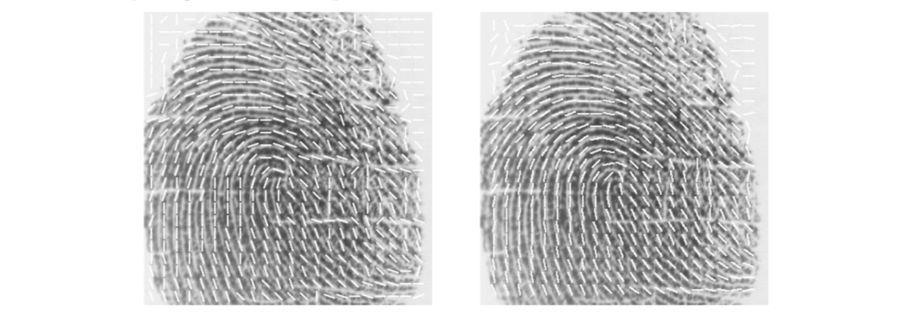
Orientation Image Estimation
The orientation image (field) is estimated from the normalized input fingerprint image. By viewing a fingerprint image as an oriented image, a least-mean-square orientation estimation algorithm is used to estimate the local orientation.
The main steps are as follows.
[1] Divide the normalized image \(G\) into blocks of size \(w \times w\).
[2] For each block, compute the gradients \(I_x\) and \(I_y\) at each pixel \((i , j)\).
[3] Estimate the local orientation of each block centered at pixel \((i, j)\) using the following equations. \[ \theta(i,j)=90^o+\frac{1}{2}\text{atan2}\left(\frac{V_1(i,j)}{V_2(i,j)}\right) \] where \[ V_1(i,j)=\sum_{u=i-\frac{w}2}^{i+\frac{w}2}\sum_{v=j-\frac{w}2}^{j+\frac{w}2}2I_x(u,v)I_y(i,v)\\ V_2(i,j)=\sum_{u=i-\frac{w}2}^{i+\frac{w}2}\sum_{v=j-\frac{w}2}^{j+\frac{w}2}(I_x(u,v)^2-I_y(u,v)^2)\\ -180^o≤\text{atan2}(x)≤180^o \] [4] Due to the presence of noise, corrupted ridge and valley structures, minutiae, etc. in the input image, the estimated local ridge orientation may not always be correct. The local orientation image can be smoothed by using the low-pass smoothing filter and the concept of continuous vector field.
Ridge Frequency Estimation
The gray levels along ridges and valleys can be modeled as a sinusoidal-shaped wave along a direction normal to the local ridge orientation.
Let \(G\) be the normalized image and \(O\) be the orientation image (field). For estimating the ridge frequency \(Ω\) image,
Step 1: divide \(G\) into blocks of size \(w \times w\).
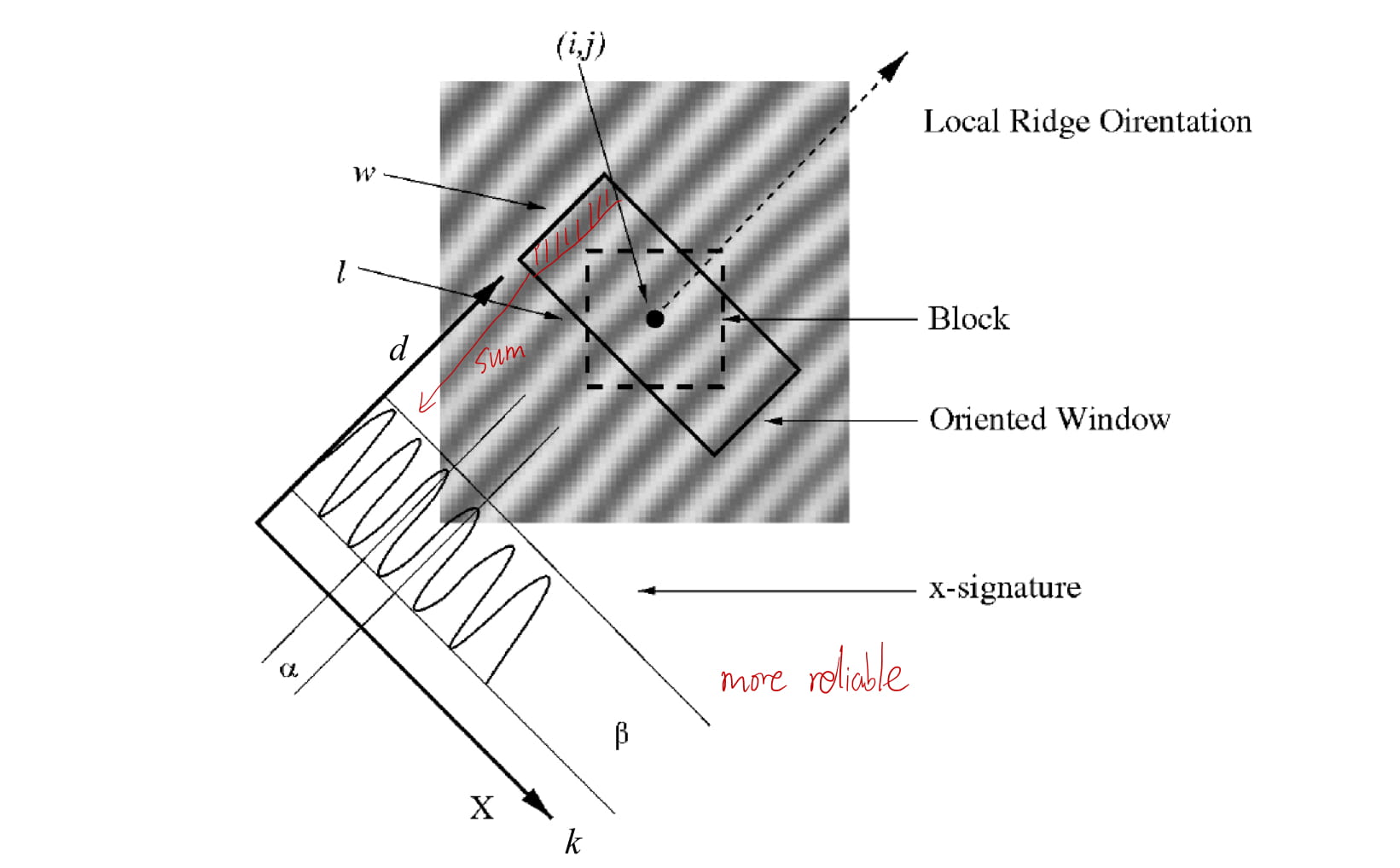
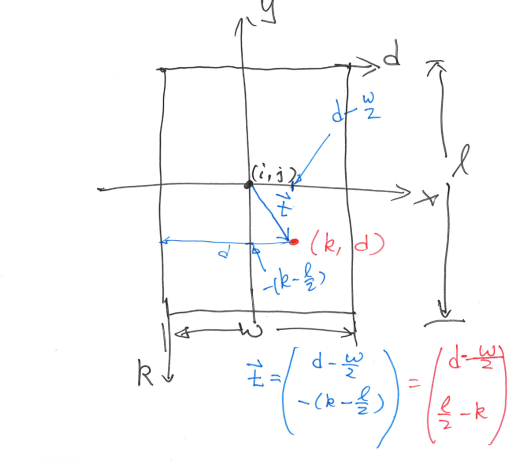
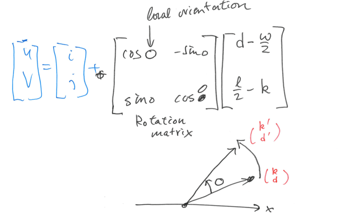
Step 2: for each block centered at pixel \((i, j)\), compute an oriented window of size \(w \times l\) that is defined in the ridge coordinate system \((k, d)\).
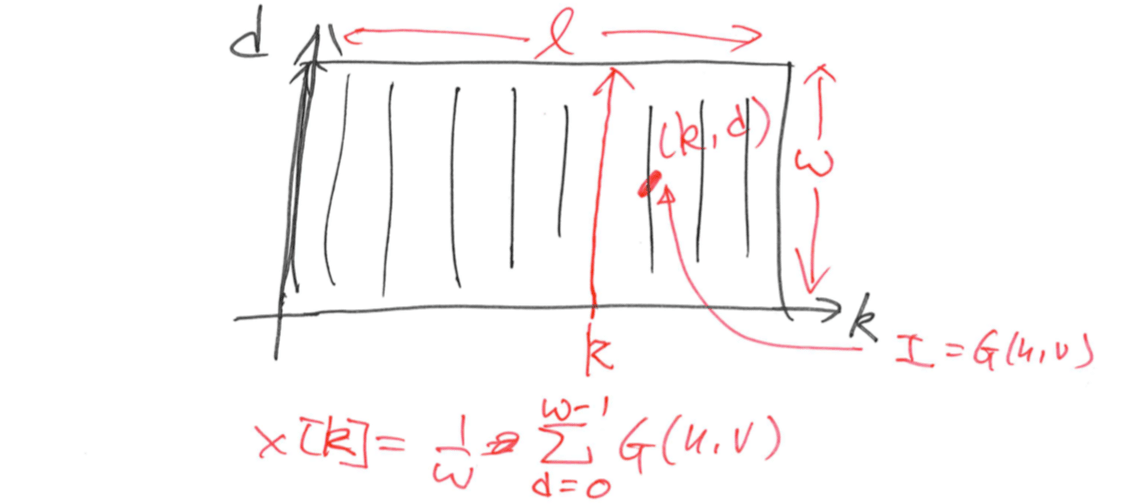
Step 3: for each block centered at pixel \((i, j)\), compute the x-signature, \(X[0], X[1], ..., X[l-1]\), of the ridges and valleys within the oriented window, where \[ X[k]=\frac{1}w\sum_{d=0}^{w-1}G(u,v)\\ u=i+(d-\frac{w}2)\cos O(i,j)+(k+\frac{l}2)\sin O(i,j)\\ v=i+(d-\frac{w}2)\sin O(i,j)+(\frac{l}2-k)\cos O(i,j) \]
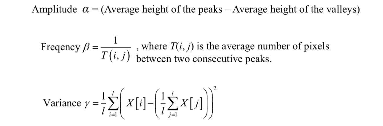
The x-signature forms a discrete sinusoidal-shape wave, which has the same frequency as that of the ridges and valleys in the oriented window. Therefore, the frequency of ridges and valleys can be estimated from the x-signature.
Let \(T(i, j)\) be the average number of pixels between two consecutive peaks in the x-signature, then the ridge frequency \(Ω(i, j)\) is computed as \[ \Omega(i,j)=\frac{1}{T(i,j)} \]
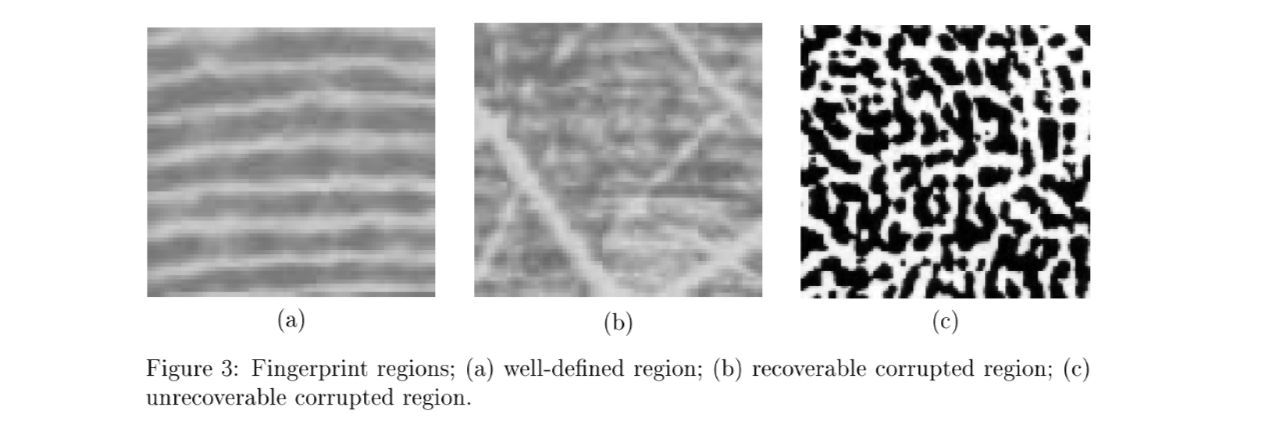
Region mask estimation
A pixel (or a block) in an input fingerprint image can be either in a recoverable region or an unrecoverable region. Classification of pixels into recoverable and unrecoverable categories can be performed based on the assessment of the shape of the wave formed by the local ridges and valleys.
Three features are used to characterize the sinusoidal-shaped wave: amplitude, frequency, and variance.
Typical fingerprint images where both recoverable and unrecoverable regions were manually labeled can be selected for region mask estimation. The above three features can be computed for each image.
Using the k-NN and clustering algorithms, each \(w \times w\) block in an input fingerprint image can be classified into a recoverable or an unrecoverable block.
Gabor Filter*
The configurations of parallel ridges and valleys with well-defined frequency and orientation in a fingerprint image provide useful information which helps in removing undesired noise.
A special (bandpass) filter, namely Gabor filter, that is tuned to the corresponding frequency and orientation can efficiently remove the undesired noise and preserve the true ridge and valley structures.
Gabor filters have both frequency-selective and orientation-selective properties and are used for removing noise and preserving true ridge or valley structures.
The even-symmetric Gabor filter has the following general form:
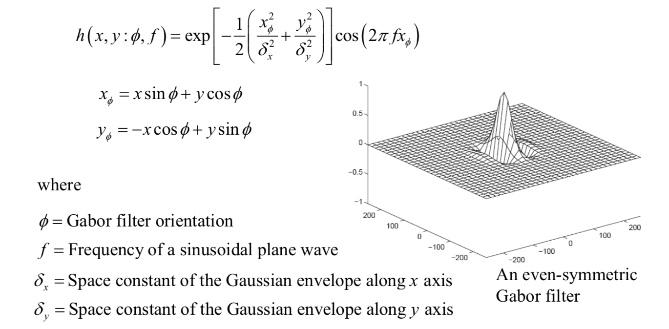
The frequency of the filter \(f\) is completely determined by the local ridge frequency and the Gabor filter orientation is determined by the local ridge orientation.
The ridge pixels are assigned a value '1' (white) and the remaining pixels are assigned a value '0' (black) in the resulting binary ridge image.
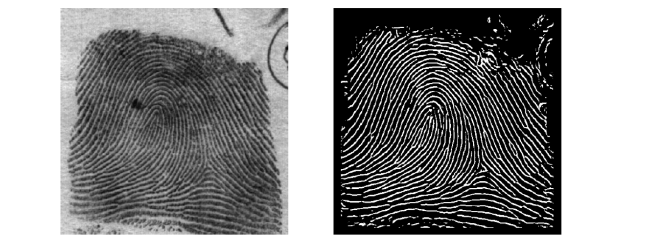
Once the ridges are located, directional smoothing is applied to smooth the ridges. A 3×7 mask is placed along the orientation field for each window. The mask containing all '1's enables us to count the number of '1's in the mask area.If the count of '1's is more than 25% of the total number of pixels, the ridge point is retained.
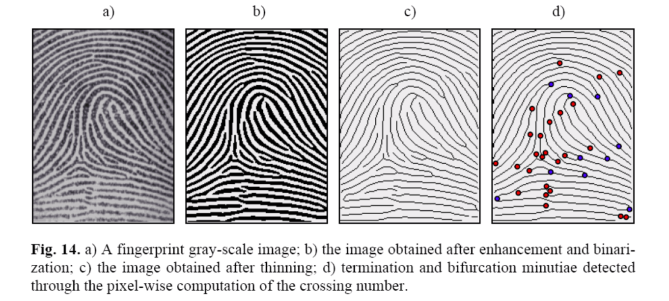
Extracting minutiae
Locating minutia points in the thinned image is relatively easy.
A count of the number of 'on' neighbors at a point of interest in a \(3\times 3\) window is sufficient for this purpose.
- A ridge end point has only neighbor in the window.
- A ridge bifurcation has at least three neighbors.
Some post-processing can be performed to further improve detection quality.

Fingerprint Matching
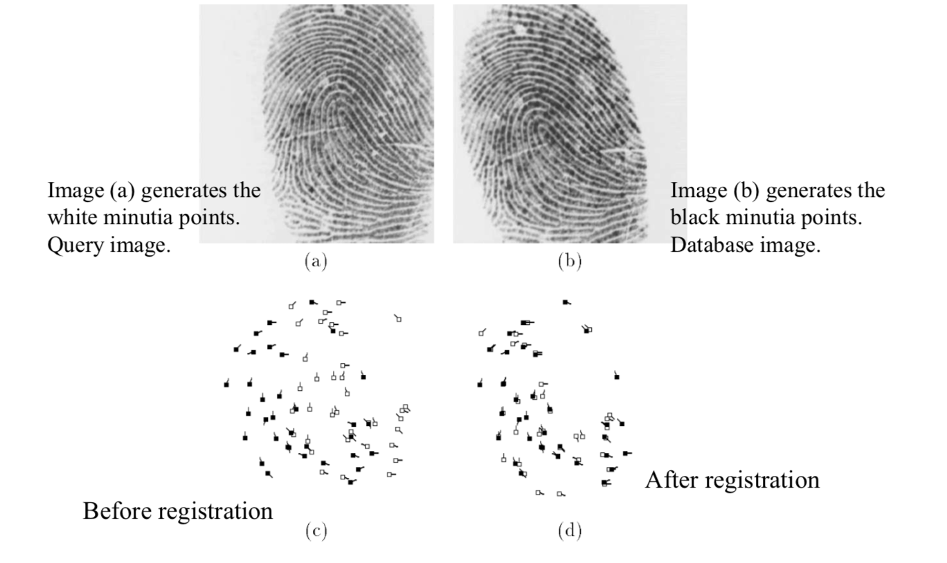
Matching a query fingerprint and a database fingerprint is equivalent to matching their minutia sets. Each database fingerprint minutia, \(p\), is examined to determine whether there is a corresponding query fingerprint minutia, \(q\).
There are three steps.
- Registration
- Minutia paring
- Matching score computation
Registration via Hough Transform
The input to the registration algorithm consists of two sets of minutia points \(P\) and \(Q\). \(|P|\) and \(|Q|\) represent the sizes of point sets \(P\) and \(Q\) respectively. \[ P=\{(p_x^1,p_y^1,\alpha^1),...,(p_x^{|P|},p_y^{|P|},\alpha^{|P|})\}\\ Q=\{(q_x^1,q_y^1,\beta^1),...,(q_x^{|Q|},q_y^{|Q|},\beta^{|Q|})\} \] Each minutia has three components: x-coordinate, y-coordinate and orientation of the minutia. Each minutia in \(P\) is rotated, scaled and translated for matching against a minutia in \(Q\).
The usual Hough transform for line detection can be generalized for point matching.
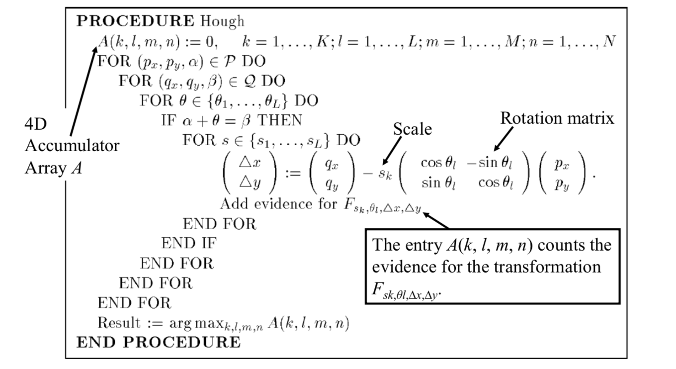
The transform has maximum value of \(A\) means that it can match as much points as possible.
Minutia pairing and score computation
After minutia registration, the minutiae need to be paired. Two minutiae are said to be paired or matched if their components \((x, y,θ)\) are equal with some tolerance after registration.
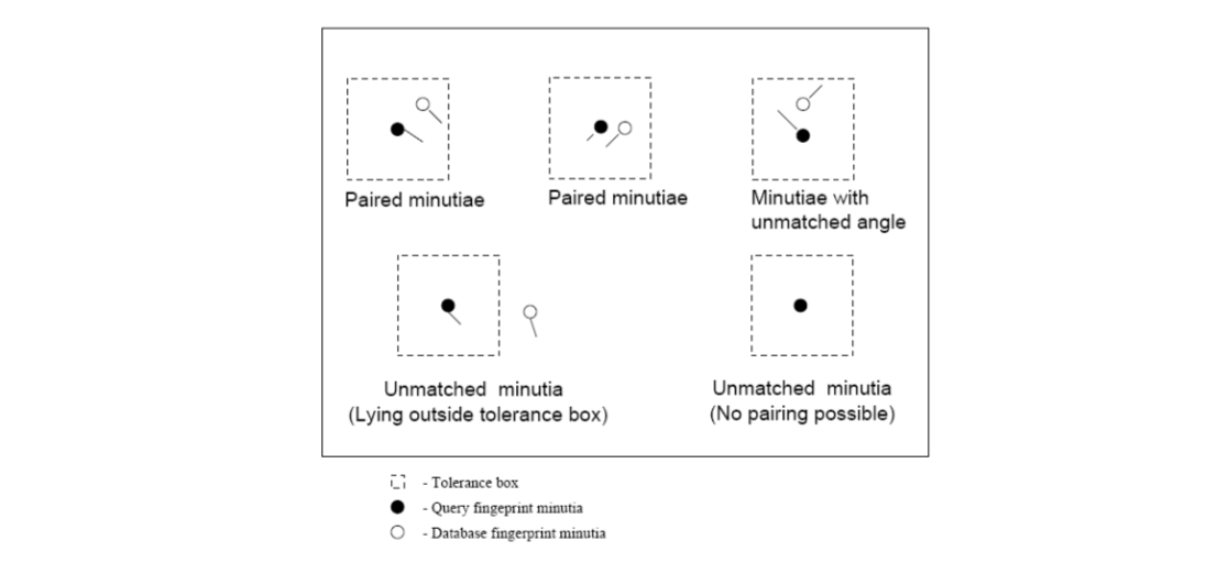
The matching algorithm is based on finding the number of paired minutiae between each database fingerprint and the query fingerprint.
In order to reduce the amount of computation, the matching algorithm takes into account only those minutiae that fall within a common bounding box. The common bounding box is the intersection of the bounding box for query and reference (database) fingerprints. Once the count of matching minutiae is obtained, a matching score is computed. The matching score is used for deciding the degree of match. Finally, a set of top ten scoring reference fingerprints is obtained as a result of matching.
FingerCode
FingerCode is a new representation for the fingerprints which yields a relatively short, fixed length code suitable for matching as well as storage on a smartcard.
The matching reduces to finding the Euclidean distance between these FingerCodes and hence the matching is very fast and the representation is amenable to indexing.
The FingerCode partitions the region of interest of the given fingerprint image with respect to a reference point. A feature vector is composed of an ordered enumeration of features extracted from the information contained in each sector specified by the tessellation.
The feature elements capture the local information by using the Gabor filterbank. The ordered enumeration of the tessellation captures the invariant global relationships among the local patterns.
These features capture both the global pattern of ridges and valleys and the local characteristics. Matching is based on the Euclidean distance between the FingerCodes.
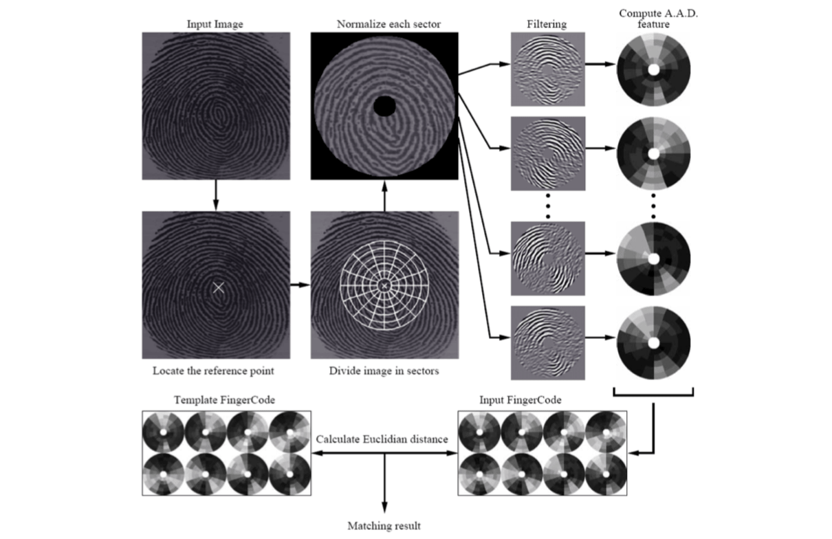
There are four steps for extracting the FingerCode.
- Determining the reference point for the fingerprint image.
- Partitioning the region around the reference point.
- Filtering the region of interest in eight different directions using a bank of Gabor filters.
- Computing the average absolute deviation (AAD) from the mean of gray values in individual sectors in filtered images to define the FingerCode (the feature vector) for matching.
Determining the reference point
Given an input fingerprint image, there are seven steps for finding the reference point.
Estimate the orientation field \(O\) using a window size of \(w\times w\).
Smooth the orientation field.
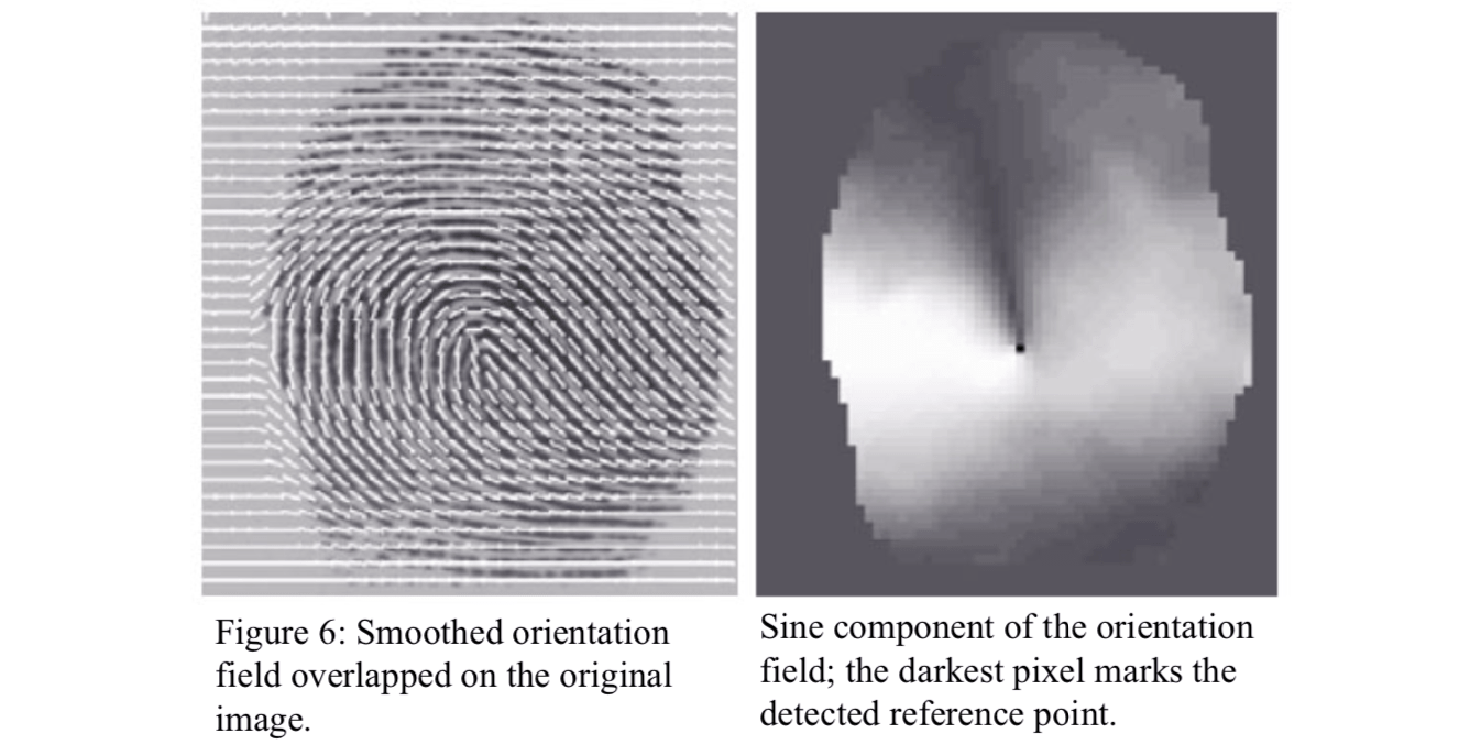
Compute the sine component \(E\) of the orientation field \(O\).
\[ E(i,j)=\sin O(i,j) \]Initialize \(A\), a label image used to indicate the reference point.
For each pixel \(E(i, j)\), integrate pixel intensities in regions \(R_I\) and \(R_{II}\), and assign the corresponding pixels in \(A\) according to the value of their difference. \[ A(i,j)=\sum_{R_I}E(i,j)-\sum_{R_{II}}E(i,j) \]

Find the maximum value in \(A\) and assign its coordinate to the reference point.
Repeat steps 1-6 by using a window size \(w'\times w'\), where \(w' < w\), and restrict the search for the reference point in step 6 in a local neighborhood of the detected reference point.
The geometry of regions \(R_I\) and \(R_{II}\) is designed to capture the maximum curvature in concave ridges.

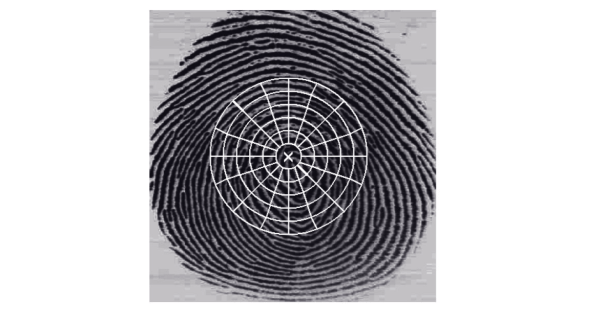
Partitioning the region around the reference point
Given the detected reference point, the input fingerprint image is partitioned into 80 sectors.
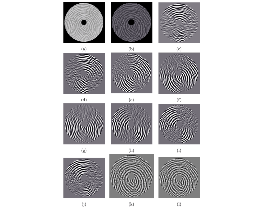
Filtering the region of interest
A minutia point can be viewed as an anomaly in locally parallel ridges and it is the information that is captured by using the Gabor filters.
Before filtering the fingerprint image, image normalization is performed separately for each sector with \(M_0\) and \(VAR_0\).
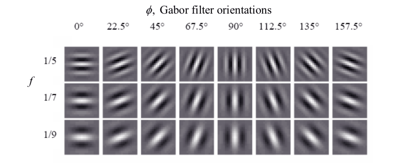
An even symmetric Gabor filter is given the Gabor filer setction. The filter frequency \(f\) can be set to the average ridge frequency. The average ridge frequency is the reciprocal of the average inter-ridge distance, which is around 10 pixels in a 500 dpi fingerprint image. Eight different values (\(0^o\), \(22.5^o\), \(45^o\), \(67.5^o\), \(90^o\), \(112.5^o\), \(135^o\) and \(157.5^o\)) are used for the direction θ with respect to the x-axis.
A fingerprint convolved with a \(0^o\)-oriented filter accentuates those ridges which are parallel to the x-axis and smoothes the ridges in the other directions. These eight directional-sensitive filters capture most of the global ridge directionality information as well as the local ridge characteristics present in a fingerprint.
Compute AAD
Let \(F_{iθ}(x, y)\) be the θ-direction filtered image for sector \(S_i\). The feature value \(V_{iθ}\) is the average absolute deviation (AAD) from the mean which is defined as \[ V_{i\theta}=\frac{1}{n_i}\sum_{(x,y)\in S_i}|F_{i\theta}(x,y)-P_{i\theta}| \] where \(P_{i\theta}=\frac{1}{n_i}\sum_{(x,y)\in S_i}F_{i\theta}(x,y)\); \(n_i\) is the number of pixels in \(S_i\).
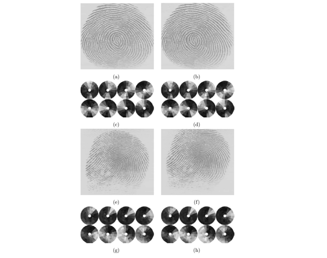
The average absolute deviation of each sector in each of the eight filtered images defines the components of the feature vector. Fingerprint matching is based on finding the Euclidean distance between the corresponding FingerCodes.